Fenwal Heat Detector Wiring Diagram
Ii 3g iic gc iecex etl 12. Visit our site to request a quote for fenwal heat detectors and other fire alarm devices from an authorized kidde fenwal distributor.

[ENG] 감지기 회로 간단하게 구성하기/ fire detector wiring / [소방전기 결선 꿀팁
T fenwal duct smoke detector wiring diagram is a simplified traditional pictorial depiction of electric.

Fenwal heat detector wiring diagram. Installation detector bases are directly mounted on the. Heat the detector for a minimum of ten seconds. Www.fenwalcontrols.com this literature is provided for.
This functionality requires the model 702u base and the 706u1b remote led indicator. Fenwal continuous fire and overheat detection system for industry ***** fss publication 602 page 4 21 november 1996 2. The fenwal sensing element consists of a small (.089 inch od), lightweight, flexible inconel tube with a nickel wire center conductor.
400 main street ashland, ma 01721 tel: Shop with confidence on ebay! Installation detector bases are directly mounted on the.
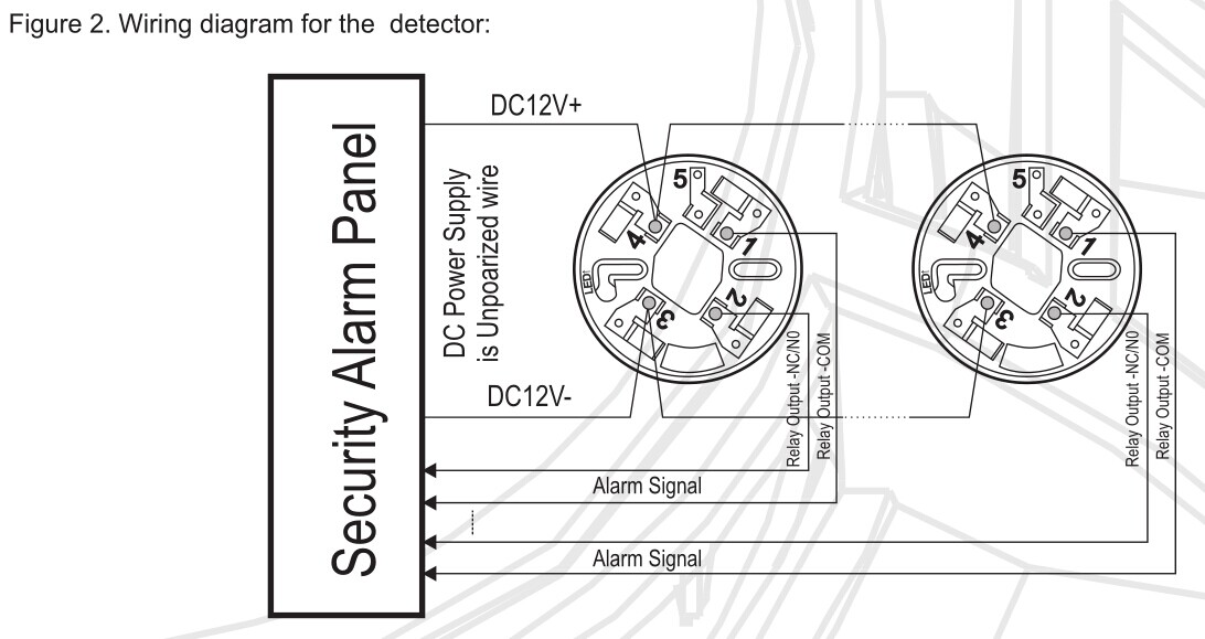
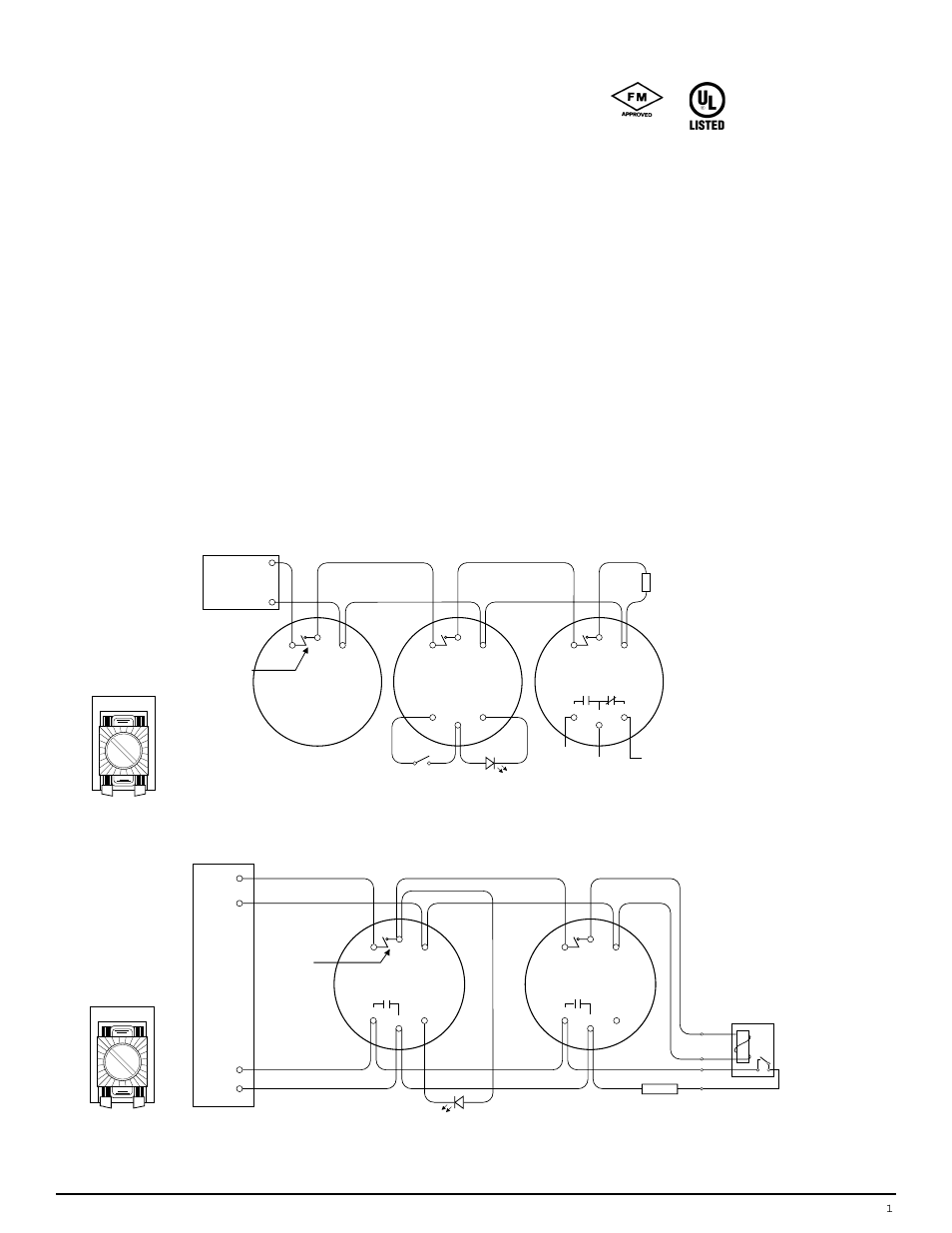
Of temperature detection feature rated at 15°f ( 8.3°c ) per minute sensing element ). A remote led indicator is available for models 721u, 721ut, and 741ut detectors. Connect system wiring to detector per figure 1 and applicable electrical codes.
Installation detector bases are directly mounted on the. The 700 series consists of two and four wire conventional photoelectric smoke, as well as photoelectric smoke with heat detectors. At 15°f ( 8.3°c ) per minute ) fenwal heat detector wiring diagram minute to awg 12 need a mains that!
The world standard in mechanical heat detectors. Nc terminal is not available on ce approved models. They can also be provided with a double thread or extended wire length to achieve the optimal mounting position and a flurocarbon protective coating can be applied for use in corrosive environments.
The case may be mounted on any surface with #6 sheet metal screws. Connect the related equipment's system wiring to the detectors terminals with the no. It is important therefore that the installation of the heat sensing system be well designed.
The tube is packed with insulation impregnated with a special salt compound and is hermetically sealed. The picture below shows the sensing element with standard connectors. Installation detector bases are directly mounted on the electrical junction boxes (3, 3.5 and 4 octagonal, 3 round or 4 square) without the need for any mechanical adapter required.
From gas stations to paint spray booths, from range hoods to large power generation systems.
Flowmeter ngukvesm19210616r5 Process controller

Flowmeter ngchfibcII0715r3 Process controller


Fenwal Controls

Aircraft systems Engine Fire Detection Systems and Fire Zones

Patent US3866687 Automatic fire extinguisher means
TTL's Blogs AlarmLine™ Linear Heat Detector Series LHD4


What Is Linear Heat Detection? Is It Right for Your

How to connect a Nest thermostat to a gas fireplace
Flowmeter ngchfibcII0715r3 Process controller

Flowmeter ngchfibcII0715r3 Process controller


R 485 2wire Wiring Diagram Wiring Diagram
Fenwal 271210 DetectAFire Heat Fire Detector Alarm

Flowmeter DKM1 Process controller,digital controller

4Wire Smoke & Heat Detector with Relay Output FT143
Edwards Smoke Detector Wiring Diagram Wiring Library
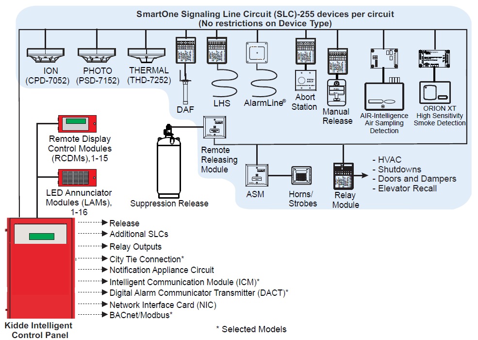
Kidde Fenwal SmartOne Devices Choose Reliable Fire Alarm
Fenwal Ignition Controller SERIES 3560 Process

Diagrams Wiring Fenwal Ignition Module Wiring Diagram

Aircraft systems Engine Fire Detection Systems and Fire Zones