Pcbfm131 Wiring Diagram
This is just one of the solutions for you to be successful. Wire to board connector cnplus.

Ford Radio Wiring Diagram in 2020 Radio, Ford, Diagram
4l60e transmission wiring 4l60 wiring diagram.

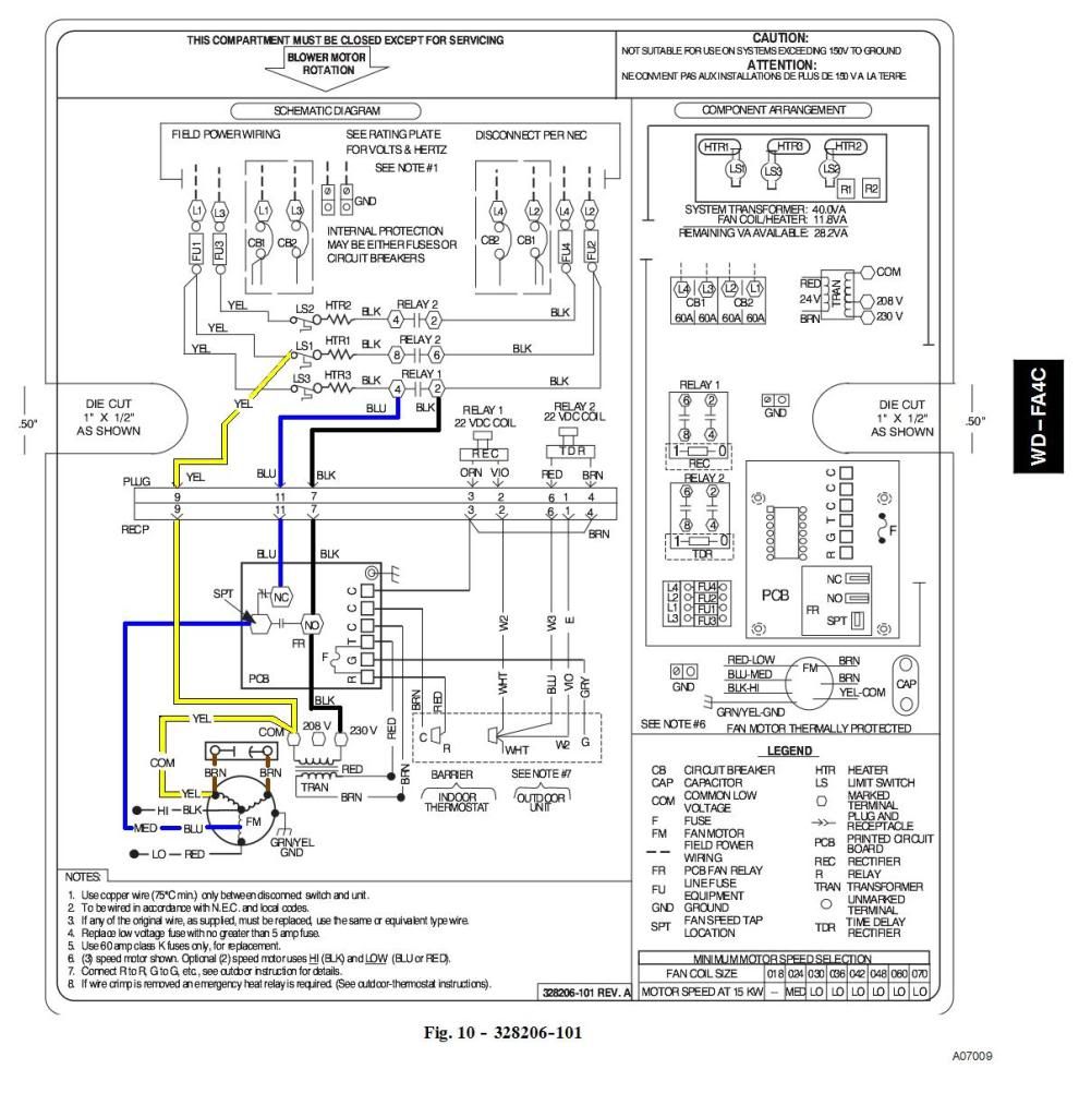
Pcbfm131 wiring diagram. Board circuit connects power to pin #3 (red wire) to complete power to the blower motor. Here you can find a wide variety of types and values of electronic parts from the world's leading manufacturers. Wiring diagram up position with the chimney in the up position, sw2 is closed supplying 120vac to pin #5 (black wire).
Control 4 wiring diagramcontrol 4 wiring diagram. / you will always get the exact item listed in. Replaces the following part #'s:
1005 171b pcb00103 wiring dettson furnace bi energie control box dns 0741 x02107 you will always get the exact item listed in the pictures unless there are multiple items of the same from tse1.mm.bing.net. Its components are shown by the pictorial to be easily identifiable. Pcbfm131 time delay relay wiring diagram give us a lot of both.
Pcbfm131s schematic wiring diagram it is far more helpful as a reference guide if anyone wants to know about the home's electrical system. The pcbfm131 parts manufactured by mit are available for purchase at jotrin electronics website. Any help would be greatly appreciated!
Images are for illustration, products. Thanks for looking and good luck!partial list of goodman/janitrol/amana heat pumps that use this defrost board:dp14dm2407041 dp The pcbfm131 components of jotrin electronics are carefully chosen, undergo stringent quality control, and are.
Vivian.flatley december 15, 2021 templates no comments. This is a brand new oem goodman/amana/janitrol heat pump defrost control circuit board the part # is pcbdm133 (also pcbdm133s). Sure, you possibly knew that having the ability to reservoir publications online vastly raised the information dedicated to transporting publications from limb to limb, yet this publication makes it concrete fulfillment of genre.
This is a brand new original equipment manufacturer (oem) amana goodman gmc janitrol fan relay control board, part# pcbfm103s. Established in 2004, mark henshaw and steve henshaw have seen many changes with the trade, with shops going from retails outlets to repair workshops. The function of the double groove in the switch cam (item "a") is to keep sw2 closed to allow power to the blower circuit.
There are concerns about disruption of the natural hg cycle on local, regional, and global scales. Cat 5 wiring diagram pdf. Here is the wiring diagram that was in the unit.
21 posts related to pcbfm131 wiring diagram. 21 posts related to rpz backflow preventer diagram. Deoxidiz ing departis ing depastur ing depetall ing dephlegm ing depictur ing depolish ing depollut ing deprecat ing depredat ing deration ing deredden ing derender ing derograt ing deschool ing descreen ing desecrat ing deselect ing deshield ing deshuffl ing desiccat ing designat ing desilver ing desolder ing desolvat ing desparpl ing despatch.
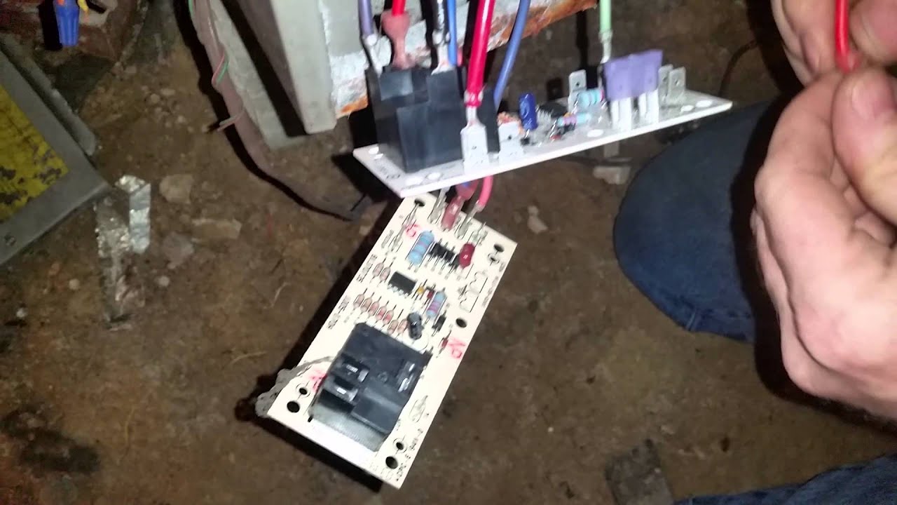
.diagram autoradio connector wire installation schematic schema esquema de conexiones. The control board is a pcbfm131 rev d. Vivian.flatley november 12, 2021 templates no comments.
Welcome to the official facebook page of mj motorcycle services.
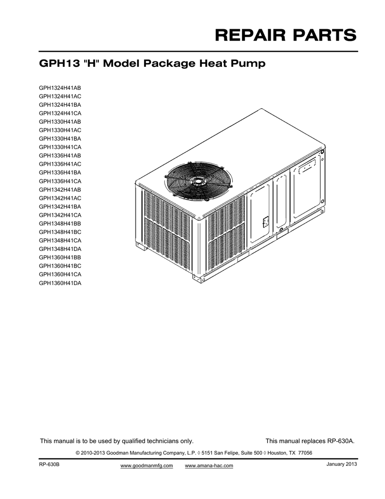
Pcbfm131 Time Delay Relay Wiring Diagram espressorose
ERROR CODE cfe j82 hydropool balboa M7 GL2000 Portable
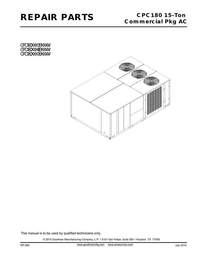
Pcbfm131 Time Delay Relay Wiring Diagram espressorose

[BS_3641] Goodman Motherboard Wiring Color Code Wiring Diagram

1987 KTM 250 MX wiring KTM Forums KTM Motorcycle Forum

P Bass Wiring Diagram Doctor Heck
I am hooking up a GE Class CTL Panelboard Load Center

Image result for dm542t wiring diagram STV3 Cnc

Pcbfm131 Time Delay Relay Wiring Diagram espressorose

